LLS - Appendix C: the Remote Control Box
PDF version
All pages in this lab
- Low Light Signal Measurements
- Introduction to Equipment (LLS)
- Introduction to Noise
- Measuring the Light Signal from a Diode
- Appendix A: SR760 FFT Interface Program
- Appendix B: SR830 Lock-In Interface Program
- Appendix C: the Remote Control Box
- Appendix D: the Phase Sensitive (Lock-In) Detector
- Appendix E: Interpreting the Data Sheet for the LED and Photodiode Data Sheet
Appendix C: The Remote Control Box
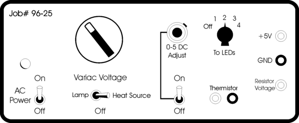
The box in the corner of the room contains the SR540 Chopper Control, a set of LEDs and a halogen lamp. To make life easier for you, all of these things may be controlled remotely from the LowLight lab station using the controller box, pictured below:

- To do anything, you'll need to turn the AC Power on.
- The Variac Voltage controls the halogen lamp, and in the future, a heat source. You may adjust the intensity of the lamp using the dial located above the Variac Voltage switch.
- The SR540 Chopper Controller is controlled by the 0-5 DC Adjust dial and corresponding switch. The switch turns the SR540 on and off while the dial adjusts the frequency.
- To turn on the LEDs, use the knob labeled To LEDS. There are three colors: red (2) , green (3), and yellow/orange (4). (1) is not currently being used.
- The Thermistor ports are not being used.
- The +5 V port provides +5 V DC.
- The GND port provides a ground.
- The Resistor Voltage port allows you to measure the voltage across the current-limiting resistor in series with whatever LED is on. See the circuit diagram below. By measuring the voltage across the resistor, you can determine both the current in the circuit as well as the voltage across the LED (5 V - Vresistor). Thus you can calculate the power being dissipated by the LED.