LLS - Appendix A: SR760 FFT Interface Program
All pages in this lab
- Low Light Signal Measurements
- Introduction to Equipment (LLS)
- Introduction to Noise
- Measuring the Light Signal from a Diode
- Appendix A: SR760 FFT Interface Program
- Appendix B: SR830 Lock-In Interface Program
- Appendix C: the Remote Control Box
- Appendix D: the Phase Sensitive (Lock-In) Detector
- Appendix E: Interpreting the Data Sheet for the LED and Photodiode Data Sheet
Contents |
Appendix A: Instructions for LowLight SR760 FFT Interface Program
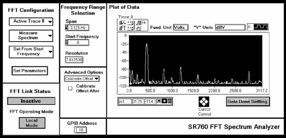
Shown above is a screen capture of the SR760 Interface Program. Following are descriptions of the various controls and displays grouped according to their location on the front panel.
FFT Configuration Group
- Active Trace Ring: This determines the active trace. Trace 0 is the default.
- Measurement Ring: This sets the measurement type between either Measure Spectrum or Measure Time Record. The default is Measure Spectrum.
- Set Span From Start/Center Frequency Ring: The default is Set From Start Frequency.
- Set Parameters: When all of the parameters from the FFT Configuration, Frequency Range Selection, and Advanced Options are chosen, Set Parameters sends them to the FFT and begins taking data. The controls are ignored after the Set Parameters button has been pressed.
Set Frequency Range Group
- Span Ring: Sets the span of the measurement. The span determines the width of the spectrum measurement.
- Start/Center Frequency Control: Sets either the start or center frequency depending on the Set Span From Start/Center Frequency Ring in the FFT Configuration Group. This option determines whether you will measure a span of frequencies centered about a frequency (which you will choose) or starting at a frequency (which you will choose)
- Resolution Display: Displays the resolution of the measurement (bin width) in Hz. (basically the Span divided by 400).
Advanced Options Group/Ring
- Calibrate Offset Option: Gives the option of calibrating the offset after taking data. The operation takes about 15 seconds, during which time no messages should be sent to the FFT (i.e. the FFT Interface should not be operated)
- Windowing Option: Sets the type of windowing to be performed.
- Linear Averaging Option: Sets whether or not averaging will be performed, what type, and how many traces will be averaged.
FFT Status Group
- Status Ring: Displays the action being performed.
- FFT Operating Mode Ring: Displays whether or not the Lock-In is in Local or Remote mode.
GPIB Address
Displays the GPIB Address. Unless the Address is manually changed on the FFT, it should be 10
Plot of Data
- Displays a plot of the data taken, the fundamental units used, and the "y" axis units used. The cursor may be operated with the cursor control or drug about on the plot with the mouse.
- Data Settling Ring: Displays whether or not the data is done settling.
Simple Operation
When the FFT Interface is run, the Lock-In is put into remote mode. The Interface then waits for you to enter the measurement parameters. When all of the parameters are chosen, press \[set parameters\]. When this is done, the Interface program sends them to the FFT, waits for the data to settle while it gathers the frequency (x-axis) information, gathers the y-axis data, plots the data, and asks if you would like to save the data. That's really all there is to it. At the end of a data run, you will be asked if you want to save the data. If you choose "yes" you will be asked for a file path, etc. The data will be saved in a spreadsheet ready format (tab-delimited).
Online Information
For online information while the program is running, just right click on the control/indicator in question and choose the Description... option.