X-ray Crystallography
This experiment is no longer available as of Fall 2012.
Contents |
X-Ray Crystallography Description
- Note that there is NO eating or drinking in the 111-Lab anywhere, except in room 282 LeConte on the bench with the BLUE tape around it. Thank You the Staff.
Modern condensed matter physics began in 1912 when Laue, Friedrich, and Knipping presented a paper on the diffraction of x-rays by crystals. They proved that crystals are periodic lattices of atoms, and ever since then this periodicity has been invaluable to studies of condensed matter. In the experiment you observe first hand the diffraction of x-rays, and will learn about crystallography. The equipment is a commercial instrument all in one package.
Note: Laue Back is no longer available. Two different methods of x-ray diffraction are used. One is Laue back (reverse direction) reflection, in which the back-scattered x-rays from a crystal are observed. A broad band of x-ray frequencies is used. The other is the Debye-Scherrer method in which a polycrystalline sample is exposed to a monochromatic x-ray beam.
You only will be doing metal and salt powder pictures. We recommend that you complete the lab on consecutive days.
- Pre-requisites: None
- Days Alloted for the Experiment: 6
- Extra Study: 4/10
- Difficulty of Lab Work: 5/10
- Analysis: 7/10
- Combined Overall: 5/10
This lab will be graded 30% on theory, 30% on technique, and 40% on analysis. For more information, see the Advanced Lab Syllabus.
Comments: E-mail Don Orlando
X-Ray Pictures
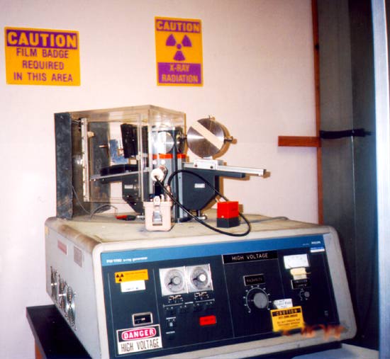 X-Ray Machine Setup Click here to see larger picture |
X-Ray Crystallography
Before the Lab
Complete the following before your experiment's scheduled start date:
- View the X-Ray Crystallography Video.
- Read How to make a Sample section Sample Preparation
- View the 'Radiation Safety Video' on a computer in the 111-Lab. Go to the shared 111-Lab drive [ U:\Advanced Lab Share\Safety Manuals and Videos ] and then click on Radiation Safety Video located in the My Computer directory on the 111-Lab Network Share Drive. After watching the video in the 111-Lab, get a pink Radiation Safety form from a 111-Lab staff person. Fill it out & sign the form for getting a Radiation Ring.
- Now complete the Radiation Safety Training Radiation_Safety After completion of Training turn in all forms to Don Orlando.
- Complete the XRA Pre Lab and Evaluation sheets. Print and fill it out. The Pre-Lab must be printed separately. Discuss the experiment and pre-lab questions with any faculty member or GSI and get it signed off by that faculty member or GSI. Turn in the signed pre-lab sheet with your lab report.
- View the Error Analysis video and Error Analysis Notes.
Suggested Reading:
- Cullity, B. D., Elements of X-Ray Diffraction, Addison-Wesley (1956).
- Kittel, Introduction to Solid State Physics (4th Ed.)
- Guinier, X-Ray Diffraction in Crystals, Imperfect Crystals, and Amorphous Bodies (Paste this link into your browser)
- Wood, X-Ray Crystal Orientation Manual\*\*
To start, look at Wood and Cullity. (Cullity is the main reference for this lab--it is clear and contains, practically speaking, nearly everything that you need to know, including examples of the calculations that you are asked to do.) Kittel is probably better for the theory of diffraction and crystal structure, and Guinier is a more advanced text.
More References
You should keep a laboratory notebook. The notebook should contain a detailed record of everything that was done and how/why it was done, as well as all of the data and analysis, also with plenty of how/why entries. This will aid you when you write your report.
Introduction
NOTE: You will only be taking Powder Camera pictures.The Laure Back has been dicontinued.
The theoretical basis for this experiment is quite simple. If a solid is represented by a collection of regularly spaced planes containing regularly spaced atoms, then the condition for a sharp maximum in the diffraction pattern of incident radiation is given by the Bragg condition:
nλ=2dsinθ
where λ is the wavelength of the incident radiation, d is the spacing between planes, θ is the angle between the incident radiation and the crystal plane, and n is the order of the diffraction. Although this model for a solid is not strictly correct (see Kittel), it is very useful and gives the correct diffraction condition.
Figure 1
In this experiment you learn to make, manipulate and detect X-Rays. With the Debye-Scherrer method, you'll use monochromatic beam, polycrystalline (powder) target and film camera to measure diffraction angles, and from that infer crystal properties. Some long powder camera exposures (overnight, but not over the weekend) might be required, so sign up for consecutive days.
(See Figure 3).
Figure 3: Debye-Scherrer Method
Your goals for this lab are to learn about x-ray diffraction, and in particular the Powder method of measuring diffraction. You will use the Powder method to determine the crystal structure and lattice parameters for several crystal samples. Useful Substances
Sample Preparation
All students must make their own sample as folows;
one copper as a good reference, one other metal of your choice, one ro two salts samples.
Powder Camera Sample Preparation --- 2/2/2011
- Architect
The Debye-Sherrer x-ray camera (powder camera) requires that a cylindrically shaped sample be placed and rotated at the center of the cylindrical camera. As the x-ray beam is less than 2 mm wide as the x-rays impinge upon the sample, the sample need only be 3 mm in any dimension. The student is required to fabricate such a sample which will fit onto the camera’s axial spindle via the sample holder (1/8“ diameter slip fit). Sample preparation is critical for producing the high-quality x-ray films that can be used to determine the crystal structure and the lattice parameters. There are several techniques to fabricate such a sample of which the following as just a few. Which technique works the best depends on the material, x-ray energy, and operator skill. However, as the x-ray energies are fixed, and the samples are known, operator skill during sample preparation has a significant impact on the quality of the results. Figure 1 shows detailed views of the powder camera sample area. (Removing the disc-shaped camera lid will produce the same view.) The sample diagrammed in red, needs to be of the appropriate size and appropriately attached to the sample holder. The sample spindle can be rotated by spinning the pulley on the camera back. The sample is a polycrystalline power, which must be contained somehow and attached to the sample holder. In the figure 1 illustration, the powder (sample, shown in red) is contained in a thin sphere (black border around the red sample), and attached to the sample holder with chewing gum (blue-green) or other appropriate adhesive. Before information about the sample structure (and the physics therein), other design parameters need to be determined (and physical insight is necessary here as well).
Figure 1: Debye-Scherrer Geometry
The first design parameter of interest is D, the diameter of the sample through which the x-rays pass, diffract, and are absorbed. If D is too small, most of the x-rays go around the sample resulting in very long exposures. If D is too large, the forward x-ray diffraction will be absorbed in sample. It should be clear then that a polycrystalline Pb sample can have a much smaller D than a polycrystalline Al sample. It should also be clear that the x-rays pass through whatever is holding the powder together (a balloon in this hypothetical case) and this whatever could also diffract x-rays and will absorb x-rays. Note that the air in the camera absorbs x-rays (how much?). It should be obvious that a Pb balloon would be a poor choice to contain the powder, whereas a thin plastic or rubber balloon might be an acceptable choice.
Figure 2 shows various sample preparation methods (contain and attach) for the powder camera. In practice, (practical side of physics) the sample needs to something that can be prepared using gloves (good safety practice) by someone (aspiring physicist) with reasonable dexterity (sans coffee) in a less than an hour and at reasonable cost. Reasonable cost is usually synonymous with either cheap materials (consumables, as in lab fees) or re-useable material (like the sample holder).
Figure 2: Some Sample Preparation Methods
We are now using the plastic shrink tubing method for making samples. It has been found they make the best samples and are easy to make.
There is a practical size limit to the paint roller technique. Above 0.5 mm coating, the sample surface becomes rough and 1 mm is about the limit for a sample/adhesive sanwich. For samples with D over 2 mm, the sample holder is modified so that a hollow plastic tube can be attached. These tubes are heat shrinkable, that is, they contract and harden on exposure to about 200 C. There are literally hundreds of different types of heat-shrinkable tubing. This clear tubing is probably Kynar (for x-ray absorption use any convenient hydrocarbon) with a 0.2 mm wall thickness. The opaque tubing is probably polyolefin.
Using a razor blade, cut a 12 mm length of tubing, square on both ends, and slip it over the sample holder. Place the sample holder in a 1/8” hole in a flat plate so that the open tube end is up. Using a creased piece of paper or foil as a guide, fill the tube with the sample. Tap the side of the tube until about 2 mm of tube is unfilled, then slip the cap over the tube. While leaving the sample in the 1/8” plate, heat all the way around the tubing for 20 seconds (heat gun on low at 5 cm distance). If the sample is not axially aligned to the sample holder, it may be moved slightly with tool pressure before it cools. If the sample preparation is unacceptable, use the razor blade to separate the tubing from the sample holder and lid and try again. The sample holders and lids are small, so that considerable manual dexterity is required to avoid hurling them across the lab.
Operation
X-Ray Source
The x-ray source consists of two units, the power supply and the copper target x-ray tube. Both have extensive safety features. There is potential for large x-ray exposure in this experiment. The main beam has an intensity of up to 10,000 roentgens per minute. Environmental health and safety will be very unhappy if you receive a dose of more than 60 millirems during the semester. (A millirem dose is roughly equivalent to a milliroentgen of radiation received.) However, there is no excuse for receiving anywhere near this amount. If you take reasonable precautions, the amount of radiation you receive should be too small to be measured.
For radiation monitoring purposes, you will wear a finger ring at all times when the x-ray machine is energized. The finger ring is to measure the amount of radiation received by your hands--it should be worn on whichever hand is usually nearer to the x-ray beam.
Turn-On Procedure for the X-Ray Machine
You must watch the videotaped "Introduction to the X-Ray Experiment" before you turn on any equipment. There is a lot to know before you can begin, including extensive safety features.
- Watch the two Videos, one for this experiment and the other the radiation safety video.
Make sure you have already filled out and signed the PINK Radiation information form.
- Get the key of the x-ray machine from a 111-Lab staff. Turn the key to the ON position. Record the Data and Machine Time On (read from the meter on the front of the x-ray machine) in the X-Ray Log Book.
- Turn on the COOLFLOW-75 water-cooling unit (On/Off switch only).
- Check to see that the High Voltage Control Knob is at 10 kV (fully counterclockwise) and that the Emission Current Control Knob is at 0 mA (fully counterclockwise).
- To turn on the X-Ray generator press the Generator Button. The white light will come on and stay on if the interlocks are all satisfied. If it goes off, then one or more of the safety requirements have NOT been met (e.g. water is off, High Voltage ≠ 10 kV, Emission Current ≠ 0 mA, or x-ray safety lights are burnt out). When the generator is producing x-rays, the X-RAYS ON orange warning lights will be on.
- Slowly increase the HIGH VOLTAGE to the desired accelerating voltage-- do not exceed 50 kV.
- Slowly increase Emission Current (mA) to the desired current-- do not exceed 26 mA.
- The x-ray tube has four ports, but we will use only port one (1). Port 1 will be used for the Powder Camera. It can be opened at any time using the shutter controls and timers. When the shutter is opened, the orange light below it will be lit, and the red indicator flag will show in the side of the housing. The shutter will not open unless a camera is in place in front of it, with the metal bar holding in the safety button below the port.
THE SHUTTER SHOULD NOT BE OPENED UNLESS THE CAMERA IS IN POSITION IMMEDIATELY OUTSIDE THE PORT. A FREE BEAM WILL SCATTER OFF ANY METAL SURFACE!
- Timers: Determine an exposure time, and set the timer for the required Port/Shutter. Each timer is located above its corresponding shutter timer control switch. The round clear plastic cover is rotated until the black pointer is set to the required time (0 to 6), while the center knob is rotated in a clockwise direction until the required multiplication factor (x1, x10, seconds, minutes, or hours) is against the arrow. The powder picture will take a minimum of 2 hours for a metal and 4 hours for a salt. To start the timer set the TIMER CONTROL switch to ON for the desired shutter (1 or 3). The red pointer will show the time remaining, and when it reaches Zero, the shutter will close.
- Shutters: You will be using Ports 1, so shutter 1 should be used. After verifying that all safety precautions have been met (camera pressed against x-ray port, plastic cover doors closed, etc.), open the necessary shutter by simultaneously pressing the lowest SHUTTERS push-button and the SHUTTERS push-button corresponding to the shutter that is to be opened.
The shutters have two colored indicator flags, one on each side of the shutter mechanism housing. The flags are mechanically coupled to the shutter, and a green flag appears when the shutter is closed, and a red flag when it is open.
You can close any shutter by pushing the O Button next to the I''' Button under the correct shutter number. Note that if you close a shutter before the timer runs out, you must RESET the timer using the TIMER CONTROL switch.
The X-Ray Generator will remain on until turned off by pressing the Generator O Button next to the lit Button Remember to turn down the High Voltage and current 1st ; it will not turn off automatically-- only the shutters will close when the timers run out. Leave the generator running while you are working for the day. If you leave the x-ray machine for the day and are not taking a picture, you should turn it off as per the Turn Off Procedure outlined below. The generator may run overnight but not over the weekend--if you need to run a picture over a Friday night, find a staff member to agree to come in and turn the unit off on Saturday.
Turn-Off Procedure for the X-Ray Machine
- Close all shutters by pushing the O Buttons.
- Turn the Emission Current down to 0 mA.
- Turn the High Voltage all the way down to 10 kV (fully counterclockwise).
- Push the Generator O push-button-- this turns all circuits off.
- Turn off the key switch and return the key to a staff member. Remember to record the Machine Time Off and other Data in the Machine Log Book.
Sample Preparation Section
Powder Camera
- Make sure that the filter holder is set for Ni.
- Before taking any pictures with any samples, check to see that the camera is properly aligned. Make sure that
- there is no sample in the camera
- both collimators are in place
- the cover is on
Note that the source collimator (coming from the x-ray source) clicks into place--push it in, and then rotate it until you feel it catch. Also put a piece of tape over the camera cover to assure that it doesn't fall off.
- If the camera seems to be not aligned, get help from Don. It should be aligned as the default.
- Place the camera in its proper position, making sure that
- the source collimator fits into the port
- the metal bar at the base of the camera pushes the safety button in.
Screw the camera holder into place at the base of the holder (right side).
- Open Shutter 1 as described in the "Shutters" section. You should see the orange light under the port come on, and the red indicator flag come up. Turn out the lights in the room. If you look at the end of the exit collimator, you should be able to see a green glow indicating that the x-rays are passing through the collimators (The green glow is caused by the x-rays striking the phosphorous screen at the end of the collimator). If you do not see a green glow, adjust the position of the camera by raising or lowering the track that the camera sits on by using the screw coming out of the bottom of the track. (If you have trouble here, ask a staff member for help.)
- Once you have seen the green glow, close the shutter, remove the camera from the port, and remove the camera cover and collimators. Whenever you remove the collimators from the camera they should be placed in the camera cover so they don't roll off the table!
- Now that the camera is properly aligned, choose a sample to start with. You should start with a metal since they don't take as long. If the sample is not already in a powder form you will have to grind it--if you do, try not to get any impurities mixed in with your sample.
- Once you have a powdered sample, get some of the powder into a capillary tube. Then seal the ends of the tube with vacuum grease, and coat the outside of the tube with vacuum grease as well. Then roll the coated tube in the powder sample so that you have powder both on the inside and outside of the tube.
- Place the capillary tube inside the brass sample tube holder. Then place the brass holder in the center of the camera chamber. Replace the collimators in the camera. Now tighten down the screw on the top of the camera. Rotate your sample (from the outside of the camera) the same way that the rubber band will rotate the sample when you attach it. Make sure the power cord is plugged in (refer to section 3.4 of the manual of Phillips PW 1720 Table-Top X-ray Generator). Gently change the position of your sample so that it will stay in line with the collimators as it is rotated. Once you have aligned your sample, release the screw. The sample holder will rotate evenly only if you back the screw out as far as you can.
- Now take the camera to the darkroom-- room 286C (right around the corner from the x-ray room), and follow the instructions posted there for loading the film. Remember that the film must remain in complete darkness until it has been developed (not even safe lights should be used)!
- After you have loaded the film and labeled your camera, place the camera back up next to the x-ray port, again making sure that the source collimator is in line with the port and that the metal safety bar is pressed against the safety button. Tighten down the camera holder screw at the base of the camera holder. Attach the rubber band to the right side of the camera so that your sample will rotate (exposing all planes to their Bragg conditions).
- Set the timer for the desired time, start the timer, and open the shutter. Use the Geiger counter to check to make sure that there is no excessive radiation.
- When your exposure is done, make sure that the port has closed (the orange light under the port should be out and the indicator flags should be green), and remove the camera from the port. Then take it back to the darkroom, keep in mind that the film must stay in the dark until it has been developed. Follow the developing directions posted in the darkroom--your piece of film should come out with the characteristic x-ray diffraction lines.
Back Laue Camera
Note: There is no reason to remove the camera from its holder--if you have problems, ask a staff member for help. Remember to make sure that the plastic cover doors are closed and locked with the screws before you open the x-ray shutter. And remember to wear your safety badge and ring!
- Mount the sample on the goniometer in the desired orientation. (Remember that to use the Greninger nets, you need to be a certain distance away from the film--check your Greninger nets to see what this distance is. The location of the film is shown by the dot on the side of the camera.)
- Put the film holder lever on "Load".
- Make sure that the knob labeled "Expose" is pushed in (in the non-expose position).
- Put a Polaroid film envelope in the holder with the side labeled "This side towards lens" (bullseye in the center) towards the x-ray tube. Push it all the way in until it clicks and then pull it out until half of the bullseye shows.
- Pull out the "expose" knob.
- Set the timer for the desired exposure time (10-20 minutes), start the timer, and open the shutter to expose the sample and thus the film.
- Check the Radiation Level around the camera with a Geiger counter.
- When the timer has run out, make sure that the shutter has closed by checking to see that the orange light under the port is out and that the indicator flags on the sides of the housing are green.
- Push the "expose" knob back in, and push the film envelope in all of the way.
- Put the film lever on "Process".
- Pull the film envelope all the way out in one smooth motion.
- After 15 seconds, pull apart the film envelope to find the developed picture. (Do this carefully as the chemicals will stain.) Remember that the photo must be coated within an hour or so to be permanent.
Procedure and Analysis
*Before you start to expose the film, check to see that there is enough development chemicals in the darkroom for your X-Ray picture.
Always use gloves to handle samples when using cobalt, Zinc, and Alumina powders.
The following is a list of available samples:
- Start with the control sample Copper
- Ferrous Suffate (FeS)
- Cobalt Powder
- Alumina Woelm (Al2O3)
- Zinc Powder
- Cupic Oxide
- Copper (you make the filings from the copper bar in the X-Ray room 286D)
- Calcium Chorlide (CaCl2)
- Sodium Chorlide -Salt (NaCl)
- Potassium Bromide (KBr)
- Potassium Permanganate (KMnO4)
- Cobalt Chorlide (CoCl2+6H2O)
Powder Photographs
You must have at least one good picture of a metal sample (2 hours) and one good picture of a salt sample (4 hours). You should use a high accelerating voltage (V) for these pictures since the K line Intensity (I) goes as: I≈Bi(V−V0)n
where n≈1.5, B is a constant, i is the beam current, and V0≈9kV for copper. (Note, however, that exposing your film for too long at too high a voltage will cause your lines to wash out.)
Lines on the powder picture film may be caused by diffraction off of surfaces other than those of your sample. Thus, you should take a picture with no sample (but with the brass sample holder in place) to identify these lines.
The Bragg Angle (θ) can be found from: 2θ180∘=SW
where S is the distance on the film from the center of the line to the point at which the directly transmitted beam intersects the film, and W is the distance on the film from the latter point to the point at which the incident beam intersects the film (see Figure 5). The beam center will probably not be the center of the hole.
Figure 5: Debye-Scherrer Geometry
In your report include a trace of each piece of film clearly showing the lines that you will be analyzing. In your calculations determine the lattice parameter a for each of your samples as explained in Cullity, and compare your values with the accepted values in the literature. Account for where each line in the pictures comes from, including any "twin" lines. Calculate the expected relative intensities of the visible lines, (again from Cullity), and determine whether these agree with your actual relative intensities. [Please note that the calculations listed above can be time consuming, and you should plan accordingly.]
Laue Photographs
Use a cubic salt crystal as your sample. Using what you know about the symmetries of the crystal, orient your sample and take pictures in the 100, 110, and 111 orientations. (Note that the angles required for 111 are not 45o, 45o.) To achieve these orientations, position the sample the way you think it should be, (e.g. sample face perpendicular to the x-ray beam for 100), take a picture (10-15 min with 50 kV at 28 mA), and see if the symmetries are what you expect them to be. If they are not, (and they probably won't be right off), change the position of the sample slightly in the direction that you think it needs to go, (ie;1 or 2 mm) and take another picture. Continue this process until you find the desired orientation (when the symmetries are what they should be), and then take a final picture. This final picture should probably be at a lower voltage ie; 30kV at 28 mA for a longer time so that the dots are clear--it is possible to get very nice looking pictures.
Remember that taking a picture with the sample in the 100 orientation does not mean that you are seeing diffraction from the 100 plane. Rather, when you have found the 100 orientation, the incident x-ray beam is perpendicular to the 100 plane and we get diffraction from planes (hkl) that meet the Bragg condition at angle θ as shown in the Figure 4. The Bragg angle can be found from tan[180∘−2θ]=rR , where r is the distance from the center of the beam to the dot on the film and R is the distance from the film to the crystal.

Figure 4: Laue Back Geometry
Experiment with different accelerating voltages--higher voltages will give you faster pictures, but will also tend to fog the film. Your best pictures will come from low voltages and longer exposure times.
In your write-up, explain how you knew when you had achieved the desired orientations. Why do you only see dots from certain planes? If you have a good picture for the 100 orientation, you should see four (symmetric) bright dots. Determine which plane is producing these dots by using either a Greninger net or the Bragg angle condition and the fact that the sample is cubic. (Feel free to do any further analysis of these pictures.) You should make a chart with the (hkl) indices and idcate the planes for the 100, 110, 111 directions. Show your calculations and the raw data. Each person should have the original picture or a copy of your partners pictures.
Procedures for Loading and Unloading X-Ray Film
You should have watched the video "Introduction to the X-Ray Experiment" by now, so this is just an outline of the steps that you need to do as a reminder. Please ask any questions that you have before you begin--remember that the majority of steps must be carried out in complete darkness!
Loading the Powder Camera
*There is a safety light which is outside the darkroom door. Please turn it on when in the darkroom developing film, off when finished. The light switch is located on the door jam inside the darkroom.
- You should, by now, have placed and aligned your sample in the center of the camera.
- Remove the cover and collimators from the camera, and place the collimators in the cover on the table where you'll be able to easily find them in the dark. The following steps must be done in complete darkness--make sure both darkroom doors are closed and that the lights are all out. Also make sure that your hands are clean and dry before you handle the film.
- Open the wooden box labeled "X-Ray Film" and remove the box of Kodak film from inside. Open the Kodak box, and remove the roll of film. Note: Always handle the film by its edges or you will get fingerprints on it!
- Slide the end of the roll into the film cutter/puncher until it reaches the end and stops.
- Cut the film using the cutter at the end--do this as one smooth motion, pushing the blade to the left as you push it down. Then re-roll the remaining film, put this back in the Kodak box, and put the Kodak box back in the wooden box.
- Now push down (hard) on the film puncher to make two holes in the film (one for each collimator). Then remove the film from the cutter/puncher, and make sure that both holes are free of any cuttings.
- Now place the film in the camera, allowing it to follow its natural curve. There are two notches at the top of the chamber that will hold the film in place: the left one is set, so push the film against this one first. Then pull the top one to the right using the screw on the top of the camera until the film is snugly in place, and then tighten the screw.
- Replace the collimators in the camera, remembering that the source (left) collimator clicks into place. (Insert it and then rotate it until you feel it catch.) Then replace the camera cover. You may now turn the lights back on.
- Tape the cover in place using masking tape, and write your name and the sample name on the tape. If you are leaving your sample to run overnight, also indicate when you will return.
Unloading the Film
- Make sure that the Ansco (black) film-developing tank is clean and dry. The lights must now be off and both doors closed.
- Remove the cover and collimators from the camera (again put the collimators in the cover), and then remove the film.
- Slide the film into the Ansco tank film holder as you saw in the video--remember to continue turning it into the holder two turns after it is all loaded in the holder.
- Put the film holder into the Ansco tank, re-place the cover of the tank, and turn it until you feel it lock. You may now turn the lights back on. (The Ansco tank is light-tight.)
- Follow the developing instructions below: Use X-Ray No Screen type film NOTE: Pour chemicals back into their own bottles where you got them.
- After you load the film into the Ansco black plastic tank. Make sure the reel is set for the proper film size spacing beforehand. The tank should be DRY. This is the only step that must be done in total darkness.
- Use Developer D-76 for 5 minutes and agitate gently with the plastic stirrer 5sec/min.
- Rinse once in water.
- Use Fixer for 5 minutes and agitate with the plastic stirrer 5sec/min.
- Rinse once in water.
- Use Hypoclear 1 minutes with constant agitation. (ie;Speeds up the rinse time)
- Rinse once in running water for 2 minutes, then open tank and shake out extra water.
- Use Photoflow 30 second with constant agitation.
- Hang film up to dry. NOTE: Pour chemicals back into their own bottles where you got them
- When you are done, put a small piece of masking tape at the end of your piece of film with your name and the sample name. Then hang the film to dry.
Always return the chemicals to their orignal containers. DO NOT Pour them down the drains.!!
NOTE: Keep the Dark room clean
The older X-ray Crystallography page can be found here.
References
- Norelco, X-Ray Powder Camera Instructions\*\*
- Phillips PW 1720 Table-Top X-ray Generator
- Ludlum Measurements 3 Survey Meter
- Neslab CFT-75 Recirculating Chiller
- Phillips Norelco X-Ray Diffraction Tube
- R. EISBERG, Fundamentals of Modern Physics X-Rays
- Polaroid XR-7 System for X-ray Crystallography
Other reprints and reference materials can be found on the Physics 111 Library Site