Holography (old)
This experiment is no longer available as of Fall 2012.
Holography Description
- Note that there is NO eating or drinking in the 111-Lab anywhere, except in room 282 LeConte on the bench with the BLUE tape around it. Thank You the Staff.
A conventional photograph records the focused image of an object on a photographic film or plate. A hologram is a photographic recording of an optical interference pattern. The amplitude and phase of light coming from the object are stored in the hologram. The phase information enables us to reconstruct the original wavefront and hence obtain a three-dimensional image in space. Viewing a hologram is like peering through a portal into a three-dimensional space in which you can see a three-dimensional image, so real that you want to reach out and touch it.
This experiment uses a 658nm diode laser as a source of coherent light which irradiates the objects, and also provides a reference beam of uniform amplitude and phase.
There are two types of holograms. One is the transmission type, which you will make, which needs the laser light to produce a reconstructed image. The other is a reflection hologram, which you will NOT make and it can be seen with ordinary white light from a bulb or from the sun.
You will learn about lasers - how they work and why - and about optical components and their adjustment. You will need skill and a light touch. This is a fun experiment. There is no right or wrong answer, but the quality of the answer is.
- Pre-requisites: None
- Days Alloted for the Experiment: 6
- Extra Study: 4/10
- Difficulty of Lab Work: 5/10
- Analysis: 1/10
- Combined Overall: 3/10
This lab will be graded 30% on theory, 60% on technique, and 10% on analysis. For more information, see the Advanced Lab Syllabus.
Comments: E-mail Don Orlando
Before the Lab
Complete the following before your experiment's scheduled start date:
- View the Holography video, {Note that we Do NOT USE Helium Laser, WE USE a Diode Laser}
- Before using the apparatus in this experiment, you must complete training in the safe use of lasers detailed on the Laser Safety Training page. This includes readings, watching a video, taking a quiz, and filling out a form.
- Complete the HOL Pre Lab and Evaluation sheets. Print and fill it out. The Pre-Lab must be printed separately. Discuss the experiment and pre-lab questions with any faculty member or GSI and get it signed off by that faculty member or GSI. Turn in the signed pre-lab sheet with your lab report.
- View the optics tutorial, a review of the principles of optics, Optics Tutorial and the Optical Tutorial Video, Energy Level (part 1) Video and Energy Levels (part 2) Video, Transistions video, and Optical Instruments video
Suggested Reading:
- W. E. Kock, Lasers and Holography: An Introduction to Coherent Optics. This is an elementary text which serves as an introduction to the subject. #QC449.K6
- B. Lengyel, "Chapter 1, Chapter 2, Chapter 5, Chapter 6." Introduction to Laser Physics. J. Wiley & Sons, Inc., 1966. #TK7872.L3.L39 (Chemistry & Engineering Libraries)
- Smith, H. "Chapter 1, Chapter 2, Chapter 3, Chapter 8." Principles of Holography, 2nd Edition (Wiley-Interscience 1969). Chapter 3 is more difficult so read it through carefully. #QC449.C64
- R. J. Collier, C. B. Burckhardt and L. H. Lin. "Chapter 1, Chapter 3, Chapter 7, Chapter 8." Optical Holography (Academic Press, 1971). This book is more mathematical than all the other references. Read at least Chapters 1, 3 and 7. Chapter 3 contains a simplified analysis of holograms without using diffraction theory. Chapter 7 contains a detailed discussion on spatial and temporal coherence and on various optical techniques. #QC449.C64
- W. V. Smith, Laser Applications, Artech House, Inc., 1970. \#TK7871.3.S62
- Lehmann, M., et al "High Efficiencies, Low Noise, and Suppression of Photochromic Effects in Bleached Silver Halide Holography"; Applied Optics: Vol. 9, No. 8, Aug. 1970, p.1948. Searchable Page
- Lehmen, Matt "Holography Technique and Practice"; pp. 1-23.
More References
You should keep a laboratory notebook. The notebook should contain a detailed record of everything that was done and how/why it was done, as well as all of the data and analysis, also with plenty of how/why entries. This will aid you when you write your report.
Introduction
Your goals for this lab are to learn about optics and its applications, and in particular to learn about and to construct holograms. To do this you will examine lasers, Michelson interferometers (Optical Tutorial), the geometry and pieces of an optical set-up, and the use of holographic film. You will end up making a transmission hologram, and a phase hologram that can be viewed with the use of the diode laser in this experiment.
The holography lab is a little different than most experiments in 111 Lab in that there is little quantitative analysis to do. You should take this as an opportunity to understand thoroughly what is happening. This lab should be fun, so please try to keep this in mind when things don't work quite right. You are not being graded on the basis of whether your holograms are of professional quality. We are much more interested in whether you understand what is going on and that you have shown some good scientific method in your proceedings.
Reflection Holograms vs. Transmission Holograms
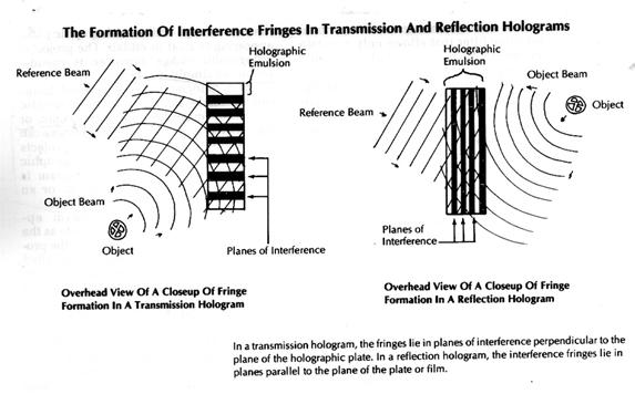
The fundamental difference between reflection and transmission is the relative position of the interference fringes recorded throughout the emulsion. The fringes are just layers of deposited silver that correspond to spaces within the emulsion where constructive interference took place. In the transmission hologram, the fringes lie in planes perpendicular to the plane of the holographic plate. In the reflection hologram, the fringes lie in planes that are parallel to the holographic plate. These planes of interference are the layer of silver within the reflection hologram, are only about 1/2 wavelength apart. The fringes in transmission hologram are usually spaced more than 1/2 wavelength apart. Holographic emulsion has usually an average width of 7 microns, or 0.007 millimeters thick.
Laser and Equipment
Laser safety goggles
You must wear laser safety goggles rated for 658 nm laser light (either the bluish OD5+ or green OD2+ goggles) while the diode laser is switched on. The beam has a power of 45 milliwatts (mW) as it leaves the laser. It is easily visible through the laser safety goggles, even when the beam power is reduced to 6 mW or less by the beam splitter. Always use caution, because 6 mW of focused light may still cause damage to the eye. Never look directly into the laser beam!
Before turning on the laser,
You should examine the optical table for misplaced objects in the laser beam path. Once these are cleared, put on a pair of the Laser Safety Goggles and turn the laser on after uncovering the protective cap.
Check for stray beams with goggles on
After you setup your optics or move them around with the laser on, you should perform a survey of the lasers beam paths to check if there are any stray beams (diffuse or specular) emanting from any part of the laser and its optics, and then document this in the laser log book in wall pocket.
- This is done by using a white piece of paper and the room lights off. Follow all of the beam paths from the laser to the film plate separately. First block the reference beam and then the object beam. The beam should refect from mirrors and NOT hit or reflect off of anything else on the Optical Table until it goes through the lens to the film plate or object. You may need to move yourself around to view the beams. This laser beam is hazardous to your eye if un-protected.
Laser Beams
Note that you need to keep the two beams Reference and Object beam separate. Look at them separately and block where you do not want the beam to go all the way to the film plate.
Diode laser
After initial turn-on, the diode laser takes about 5 minutes to stabilize (mainly thermally) and should be left on during your day of work. You should block the beam with a black metal shield to prevent any laser light emission when NOT in use. Clean up the beam with the available iris diaphragms; observe the diffraction effect that occurs when the iris aperture is made small and plan accordingly. You will need to block other beams that interfere with your exposures. There are a number of beams coming off of the beam splitter due to the multiple optical interfaces; note the correct one and block the others. See the diagram for making a hologram. Use a piece of paper or a gray card to locate the beam. Always be careful never to look into the beam, especially during alignment procedures, so be careful both for yourself and anyone else who is nearby. This is particularly important when you are viewing a hologram. Also, keep the door to the holography room closed when you have the laser on and block off the beam when entering or exiting the room.
Laser power meter
The laser power meter is a photodiode-based detector that measures laser beam power and wavelength. For best results, set the scale to automatic. Do NOT leave the meter on a low scale while in manual mode; this will damage or destroy the high sensitivity circuits.
Digital oscilloscope
Familiarize yourself with the basic operation of the oscilloscope. One useful feature of the device is the ability to take a single measurement and then stop; this can be accessed using the Run/Stop buttons in the upper right corner of the control panel. The oscilloscope also includes a USB port on the back, allowing traces and other data to be saved to an external USB drive.
Optical components
Look over the various optical components: variable beam splitters, front surface mirrors, neutral density filters, baffles, lenses, apertures and an exposure mask. !!!Handle all optics by their edges. No thumb prints on the surfaces, please!!! Clean dirty optics gently with an air duster can. See 111-LAB staff if the mirrors or beam splitter require more cleaning than this! It is up to you to keep the optics clean. In order to keep the mirror surfaces from degrading or collecting dust, please cover the mirrors and beam splitter at the end of each day with the large plastic bags provided.
Optical table
The 4 x 8 foot table is isolated from the vibrations of the building by air shocks. The air is supplied from the building through a filter regulator to the four shocks inside the legs under the table. Caution: DO NOT lean on the table. The air line comes down from overhead to the table and legs, so exercise caution when working around it.
Photographic plates
*Before you expose a film plate please locate the development chemicals in the darkroom to see that they are available.:To record the holograms, we use 2-1/2 x 2-1/2 inch glass photographic plates of type PFG-01 for both transmission holograms. They should be handled by the edges, in complete darkness. Avoid contact with the surface of the plates as this can scratch the emulsion. To tell in the dark which side is the emulsion side, gently touch the surface near a corner of the plate. The emulsion side will feel sticky to your fingers, especially if your finger is slightly damp. The plates are very expensive. You should only need 4 to 6 plates so don't be careless, but of course you're here to learn not to conserve photographic plates. See Hologram Development Procedures for specific instructions on developing your holograms. More information on the plates themselves is given in the Film Data Sheet.
Procedure
Before you get started, view the Laser Safety Video [Laser Safety Training] and complete the Laser Safety Quiz. Note that you MUST wear the provided laser safety goggles at all times while in the Holography room and keep the door properly closed. Have a 111-LAB staff member check out your setup before exposing the first plate.
Initial Setup
- Familiarize yourself with the apparatus in the holography room. There is a variety of optical equipment; figure out what each piece is and does beforehand. Familiarity and proper planning will save time during construction and alignment, and reward you with excellent results. There are also some sample holograms in the room, which should give you an idea of what you're trying to produce.
- Though the power meter's LCD does not have a backlight, it is still a good practice to shut it off or block it from the film plate when making a hologram.
- Check the door and window for light leaks; fix any leaks with the provided black tape.
Alignment Considerations
- Always ensure that the laser beam is level, especially when building the interferometer; this makes it considerably easier to get fringes and is a good general practice when working with lasers.
- The variable beam splitter surface is not perfectly vertical, and its deviation from vertical changes as the beam splitter is rotated. This is not so much of a concern when making holograms, but when building the interferometer, the mirror base can be shimmed with pieces of paper to get a truly vertical surface. Plan accordingly.
- Use an iris right in front of the diode laser to create a more circular beam and also prevent back reflections from the interferometer from getting into the laser cavity and causing instabilities.
- Diffraction rings in the beam are almost always generated by dust particles on the mirrors or lenses. Use compressed air on the mirrors (get 111-LAB staff to help with higher level cleaning), and carefully wipe the lenses with lens paper and methanol.
Stability Measurement
Since any vibration during the exposure of the photographic plate can destroy the holographic process, it is important to determine the stability of the table and optics.
- In order to isolate the optical table from vibrations, the table is seated on four self-regulating air ride legs. The pressure in each is automatically maintained at 50 lb/in2. Observe that lifting object onto and off of the table will cause one or more of the table legs to adjust itself.
- Set up a Michelson interferometer on the optical table as illustrated below:

Michelson Interferometer setup
Set the lengths of the two arms on the interferometer approximately equal, to ensure good interference fringes. Mask off the power meter detector with black tape, leaving a small hole in the center. Position the hole so that it allows light from only one fringe to reach the detector surface. Make sure that the power meter is set to the proper wavelength for the 658 nm laser, and that you have chosen a scale appropriate for your power readings (automatic usually works best). Connect the output of the power meter to the digital oscilloscope input with a BNC cable. Set the time scale to between 30 seconds and 60 seconds, and adjust the vertical scale to a setting appropriate to the power meter's signal. Optionally, save traces from the digital oscilloscope to an external USB drive using the USB port in back.
All of interference fringes, good |
Part of interference fringes, okay |
- You should see the signal on the oscilloscope wander around and the fringes on the wall move as the interferometer experiences various instabilities. Determine from the oscilloscope output the average time lapse between large fluctuations in power of the fringe you are observing. Why should the exposure time in making the hologram should be always less than this time? Why is an order of magnitude measurement sufficient?
- How short does the temporal coherence length of the laser need to be in order to be a limiting factor for fringe stability? Suppose you manage to have the two path lengths exactly the same. Will the coherence length of the laser be a problem for you for reasonable assumptions? Note that a typical linewidth (from which you can deduce the temporal coherence length) of a free running diode laser can be on the order of GHz.
- What instead are the limiting factors for the fringe stability? Find out experimentally what limits the fringe stability in practice and draw conclusions on how your presence in the room might affect the hologram quality.
- What is the difference between temporal and spatial coherence. To what extent do you need spatial coherence for the holograms?
Making the Holograms
The critical parameters for hologram creation are laser beam power and exposure time (and object-reference beam angle for transmission holograms).
- Because it is the easiest to make, start with a transmission (absorption) hologram. Look up the parameters of the photographic emulsion for its resolution and emulsion thickness in the Film Data Sheet. The PFG-01 film plates can resolve 3000 lines/mm. From this information, calculate the maximum angle which can be subtended between the object and reference beam so that (a) the film can resolve the interference fringes and (b) the hologram will be a plane hologram. Then set up the optics for making a plane absorption hologram within the limits of these calculated angles. Record the geometry you use, including the relevant lengths and angles so your hologram can be viewed later. Use the power meter to record the intensities of the reference and object beams incident at the photographic plate. The ratio of the intensity of the reference beam to the object beam should be between 4/1 and 10/1, but start with a ratio of 4 to 1. The absolute energy per area (or fluence) should be 100 microjoules/cm2 in order to produce an optical density of 1.5
- Choice and placement of an object. Each point or small area on the object acts as a source of light, and should scatter light in all directions. A shiny metal surface doesn't do this, but instead is like a mirror that reflects light specularly rather than diffusing it. You need diffusely reflecting surfaces with differing amounts of reflected light. Evaluate the light that will reach the photographic plate by putting your eye there; as always, use caution when doing this. If you can't see the object clearly and uniformly irradiated, you will not get a good hologram. The reference beam must be as uniform as possible, and must cover all parts of the object that you can see from the plate position. At best, what you see is what you get, and nothing more, often less.
- When you are ready to make your first hologram, get a plate. Take an empty black light-tight plastic box from the holography room, put your names on a piece of masking tape on the box, and find a staff member to get one plate. This box will be yours for the duration of the semester. Remember that the plate must be handled in complete darkness until after it has been developed. Also use common sense when working with the film: handle it by the edges to avoid fingerprints; store the plate emulsion side up in the box.
- Develop the plate according to developing procedure #1 in Hologram Development Procedures. The darkroom is Room 286C, the third door on your left as you walk into Room 286, and is shared with the X-Ray experiment. Remember to close BOTH doors in the darkroom. In the darkroom you should find all of the chemicals necessary to develop and fix the plates, and trays in which to pour the chemicals. Pour the chemicals back into their containers when you are done for the day - DO NOT pour them down the sink drain! Before you take your plates out of their black box, give some thought to what you will be doing when you develop. Once you begin, you want the process to go as smoothly as possible Also that it is your responsibility to keep the darkroom clean when you are done. This means not dripping chemicals on the floor. Rinse your hands each time after you have had them in chemicals. Don't drip fixer into developer, or you will ruin it. Once developed, fixed, rinse, and dried, mark each plate with your names, the date, and what it is (object and hologram type). It is up to you to protect your film plates from damage or misplacement, so please be careful.
- Place the hologram in the holder in which it was exposed. Remove the object, and look through the hologram. You should see the object just as it was when you made the exposure. Observe your hologram and record the position and size of the image compared with the object. Determine whether the image is real or virtual, and pseudoscopic (inside out) or orthoscopic (right side out). In the write-up you should explain whether the characteristics (such as virtual or real, magnified or reduced) of the image you observe agree with what you expect from your optical arrangement. If the hologram can be seen by eye, than it probably can be seen with a camera; taking a photo or two of your masterpiece is useful both for your report and for posterity (especially in the case of the transmission holograms).
- In the case that a hologram does not turn out (which will undoubtedly happen at least once), stop and think before you ask for another plate. What went wrong? What are you doing to correct it? Troubleshooting is a process that requires time and patience. Do not simply try the same thing over and over hoping that your problem will go away. Most of the time, the issue will be related to your laser power vs. exposure time.
- Make a phase hologram by using the same set-up with a longer exposure time, say 2-3 times longer. The optical density of the hologram is between 2 to 3. [Optical Density = log(1/Transmittance)\] Develop the phase hologram by procedure #2 and observe and analyze the hologram as above.
- For the reflection hologram you might want to choose a slightly longer exposure time. Why?
Hologram Ray Diagrams
Figure 1:
Figure 2:
Report
Your report should include explanations of the following:
- The principle and operation of the Diode laser.
- How an image is recorded by a photographic plate.
- The grainy appearance of any object illuminated by laser light (called laser speckles).
- The difference between plane and volume holograms; absorption and phase holograms; real and virtual images; pseudoscopic and orthoscopic images.
- How to obtain a magnified image with a hologram.
- Your report should also include your holograms (in the film box) marked with masking tape that gives the hologram type, orientation, and your names. You should have an absorption hologram, phase hologram, and reflection hologram. Include all of the film plates that you used and mark which ones were successful.
Film Data Sheet The VRP-M and PFG-01 Materials
Characteristic curves for these emulsions, showing spectral sensitivity versus wavelength, are shown in figure 1. The VRP-M light sensitivity (CW radiation) is seen to peak at approximately 75 microJoules/cm2 and that of PFG-01 (CW radiation) at approximately 100 microJoules/cm2. Figure 2 shows the optical density after exposure by CW radiation and development versus energy.
Figure 1: Spectral sensitivity curves For VRP-M (black) and PFG-01 (grey) |
Figure 2: Characteristic curves for VRP-M (left) and PFG-01. |
Grain size characteristics for the VRP-M and PFG-01 emulsions are presented in Figure 3. The diffraction efficiency versus exposure for reflection holograms recorded on PFG-01 (using a CW laser) and on VRP-M (using a pulsed laser) is presented in figure 4. The maximum diffraction efficiency is seen to be >40% for both emulsions. Material life is more than two years.

Figure 3: Grain size distribution Curve for VRP-M and PF-01 |
Figure 4: Diffraction efficiency curves for VRP-M and PFG-01 |
The VRP-M emulsion may be used equally well with frequency-double pulsed Neodymium lasers as with green CW radiation. The PFG-01 emulsion, however, is not sensitive to pulsed radiation from the Ruby laser and as such should be only used with CW sources. Emulsions used with pulsed radiation should be post-sensitized with the technique of latensification (see section below).
Description of PFG-01 (This is the film we use)
Fine-grained red sensitive holographic plates and film designed for transmission or reflection hologram recording. Average grain size is 40nm, resolving power more than 3000 lines/mm, spectral sensitivity range 600-680nm (including 633nm, 647nm).
Summary of Technical Specifications
| Parameter | PFG-01 |
| Holographic Sensitivity | |
| @ 457nm CW microJoules/cm2 | |
| @ 488nm CW microJoules/cm2 | |
| @ 514.5nm CW microJoules/cm2 | |
| @ 526.5nm 30ns pulse with latensification microJoules/cm2 | |
| @ 633nm microJoules/cm2 | 100 |
| Gamma | >6.0 |
| Max Density on Characteristic Curve (Dmax) | <4.0 |
| Fog Density (DO) | <0.01 |
| Resolving Power (R), mm-1 | 3000 |
| Max. of Spectral Sensitization, nm | 633 |
| Swollen Emulsion Layer Strength after Chemical Processing, H (gm force) | 900 |
| Adhesion between Emulsion layer and Base after chemical processing (Class A-F) | A-C |
| Deformation Temperature of Emulsion Layer in water (tdef), °C | >90°C |
| Emulsion Layer Thickness (microns) | 7 to 8 |
| Normal Diffraction Efficiency for Reflection | |
| @ 457nm, % | |
| @ 488nm, % | |
| @ 514.5nm, % | |
| @ 526.5nm, % | |
| @ 633nm, % | >40% |
| Geola Guaranteed Storage Period at 4°C, 30% Humidity | |
| Film Roll (months) | 18 |
| Cut Sheets (months) | 12 |
| Plates (months) | 18 |
Development Procedure No. 1 (Non-Bleached Transmission & Reflection Hologram)
CLOSE BOTH OUTSIDE DOORS TO room 286C, TURN OFF ALL LIGHTS, AND WORK IN COMPLETE DARKNESS. Turn on the Safety Light (white switch box on door jam) (this light is outside the room door). Procedure takes approximately 25-30 minutes to complete and is best done with another person.
- DEVELOPMENT: Five (5) min. in Kodak D-19 Developer with constant agitation. Most of the development occurs during the first minute. Agitate the developer by tipping the tray regularly. It is important to keep track of the time as taking out the plate too early or leaving it in too long will under- or overexpose it.
- RINSE: Thirty (30) sec. in running water with constant agitation.
- FIXATION: Two (2) min. in Kodak Rapid-Fixer with constant agitation.
- RINSE: Thirty (30) sec. in running water with constant agitation.
- LIGHTS MAY BE TURNED ON
- RESIDUAL FIXER REMOVAL: One and a half (1-1/2) min. in Hypo Clearing Agent with constant agitation.
- WASH: Five (5) min. in running water.
- RESIDUAL DYE-SENSITIZER REMOVER: Five (5) min. in Methanol with constant agitation.
- RINSE: One (1) min. in running water.
- PHOTO-FLO: Rinse the plate for thirty (30) seconds with constant agitation. The Photo-Flo reduces the surface tension of water and prevents water spots from forming on the emulsion.
- DRY: Air dry at room temperature. Stand plate on edge.
- RETURN ALL CHEMICALS TO THEIR CONTAINERS!!!
DO NOT POUR CHEMICALS DOWN THE DRAIN! POUR them BACK into their respective bottles!!!
Development Procedure No. 2 (Bleached Phase Hologram)
CLOSE BOTH OUTSIDE DOORS TO room 286C, TURN OFF ALL LIGHTS, AND WORK IN COMPLETE DARKNESS.
- DEVELOP as before (steps 1-9 in procedure #1).
- LIGHTS MAY BE TURNED ON WHEN BLEACHING
- BLEACH: Agitate the plate in bleaching solution until the metallic silver has been completely converted from black to an almost clear blue. The bleaching solution is composed of 20 grams of cupric bromide (CuBr2) per liter of water.
- WASH: Five (5) min. in running water.
- PHOTO-FLO: One-half (1/2) min. with constant agitation.
- DRY: Air dry at room temperature.
- RETURN ALL CHEMICALS TO THEIR RESPECTIVE CONTAINERS!
DO NOT POUR CHEMICALS DOWN THE DRAIN! POUR them BACK into their respective bottles!!!
References
- Saxby, Graham, Manual of Practical Holography, Focal Press 1991. #TA1540.S35
- Martens, A.E. "Lasers A Popular Discussion", & Snow, K.A.; Bausch & Lomb, pp. 1-12.
- Carcel, J.T, et al "Simplification of Holographic Procedures"; Applied Optics: July 1966, Vol. 5, No. 7, pp. 1199-1201. Searchable Page
- Lehmann, M., et al "High Efficiencies, Low Noise, and Suppression of Photochromic Effects in Bleached Silver Halide Holography"; Applied Optics: Vol. 9, No. 8, Aug. 1970, p.1948. Searchable Page
- Landry, John "Coffee-Table Holography"; Journal of the Optical Society of America:Vol. 56, No. 8, Aug. 1966, pp. 1133. Searchable Page
Some Books on Lasers and Optics:
- Strobe, G.W. "Sharpening Images by Holography"; New Scientist: Vol. 23, Sept, 1971, four pages.
- Leith, E.N., & Upatnieks, J. "Progress in Holography"; Physics Today: March 1972, pp. 28- 34. Searchable Page.
- Siegman. Lasers. University Science Books, c1986. UCB Physics QC688 .S561
- N. V. Karlov. Lectures on quantum electronics. Moscow : Mir Publishers ; Boca Raton, Fla. : CRC Press, c1993. UC Berkeley Physics QC689 .K3713
- W. Demtroder. Laser spectroscopy : basic concepts and instrumentation. Berlin ; New York : Springer-Verlag. #QC454.D46
- K. J. Kuhn. Laser Engineering. Prentice-Hall, 1998.
- S. G. Lipson, H. Lipson and D. S. Tannhauser. Optical Physics. Third Edition, Cambridge University Press, 1998. #QC395.2.L56
- M. Young. Optics and Lasers. Springer-Verlag, 1993. #TA1520.Y68
- C. C. Davis. Lasers and Electro-Optics. Fundamentals and Engineering. Cambridge, 1996. #TA1675.D38
- Helium-Neon Gas Laser: Description, Experiments Bausch & Lomb, pp. 1-36, not in use any longer, instead we use a diode laser.
- There is extensive literature on both lasers and holography so it is impossible to list them all. Some of the references listed here are classics and unfortunately out-of-date. You are encouraged to go to the library and find more recent references on holography. If you come across any good ones, let the staff know.
Other reprints and reference materials can be found on the Physics 111 Library Site